

The Accordion™ architecture
Software and hardware concepts

Revision History
|
Revision |
Author |
Changes |
|
0 |
Daniel Rhodin |
First draft |
|
|
|
|
Table of Contents
Introduction to Accordion™
Accordion™ is a modular build system for a test- and measurement interface. Developed by E# to maximize reuse and flexibility for virtually any measurement needs.
Every piece of electronics will require some kind of test interface in order to be tested and verified. The level of sophistication varies but serves a few clear purposes:
-
Provide power
-
Connect to one or several communication buses
-
Generate appropriate stimuli in terms of analog- or digital signals
-
Measure analog or digital signals
In addition to providing a test interface to the DUT itself, it might also provide test fixture control. A test fixture could range from a very simple jig that fixates the DUT, to a complex machine with automation capabilities.
The challenge with test interfaces in general is that the products they should connect to are vastly different. Even within one company, the product range could put different requirements on a test interface product. It becomes clear that there is no “one size fits all” solution that can be employed.
Often, the test interface is designed in-house as there are no off-the-shelf products that suit the specific requirements in each case. Making a test interface solution can be very time consuming, locking up skilled R&D engineers for months or years and the constant updates and versions become increasingly hard to handle.
A test interface is not only a piece of hardware. Someone needs to make software and firmware drivers for it, allowing it to be used for manufacturing. Often, a complete graphical user interface is also developed for troubleshooting and debugging capabilities.
The effort spent by internal R&D teams to source, maintain and support the solutions can be very significant, impacting on the design effort on the actual products that should be developed.
Accordion™ brings a fundamental shift in what is possible.
With Accordion™, everything is a module: DUT connections, communication buses, fixture control, measurement capabilities, stimuli, subsystem control, everything is a module. Even the software is completely modular. This stems from the realization that nothing can be fixed when the requirements could be vastly different.
The strength of the Accordion™ concept lies within the build system and the subsystem that connects all parts of the system together. Even if the connectors can be different for a specific DUT, they typically share many traits, allowing for standard (or completely specific) modules to be used to form the complete solution. For example, many DUTs will require communication buses, such as I2C, UART, USB or JTAG. The difference could be the I/O voltages and the connector, which in Accordion™ is solved by a module that provides this adaptation. Another common requirement is power and analog measurement capabilities, E# provides standard modules. As the modularity is in the heart of Accordion™, it can always be adapted to virtually any required functionality.
Accordion™ brings a tremendous opportunity for engineering managers to unlock man-years of senior developers that now can focus on the company’s products instead of an internal test interface product.
Architectural overview
As mentioned in the introduction, Accordion™ is completely modular. At its core, there is a bus system with defined functionality and power that allows for vastly different applications.
Module Types
There are currently 4 different types of modules that is supported in the Accordion™ build system:
|
Module Type |
Features |
Comment |
|
SO-DIMM |
260-pin, 100 user signals, several form factors |
Most of E# measurement modules are of this type |
|
M-SLOT |
Robust, high current |
Power-hungry type of modules, such as PoE module and PSU module uses this type |
|
N-slot |
100 user signals, very high density |
Only used to expand the AGENT™ top with new functionality |
|
EXPAND |
24V, differential I2C distributed over M8 industrial connector Up to 30 meter cable, cascadable |
Used for functions that are suited to be placed elsewhere than the main unit. It could for example be controlling relays or power supplies in test fixtures |
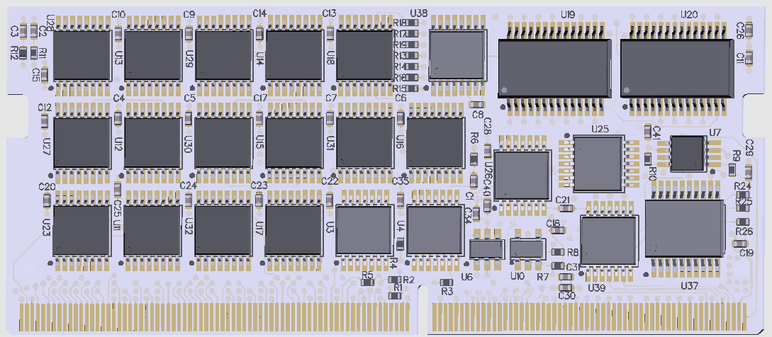
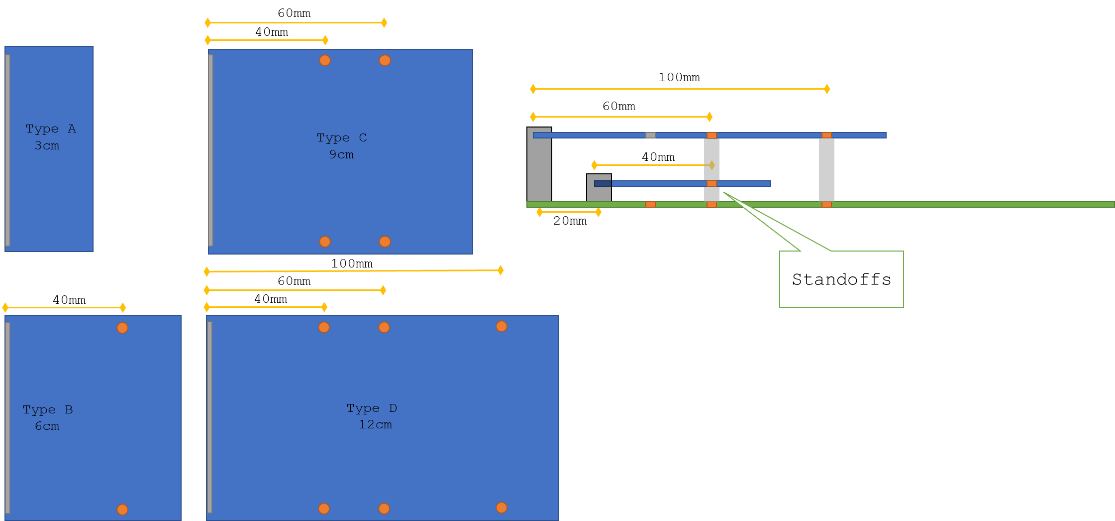
SO-DIMM
There are four different form factors allowed, Type A-D.
It is possible to stack two SO-DIMMs on top of each other.
Example:
N-SLOT
Example: 6xIDC 20 pol connector board
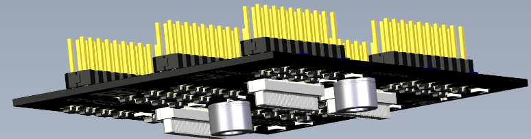
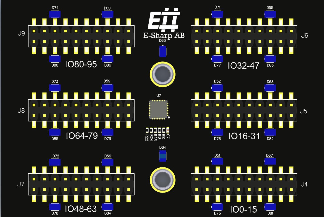
The N-TOP slot (total 4) on AGENT™ is primarily used to allow for connector adaptation for measurement modules.
EXpand™
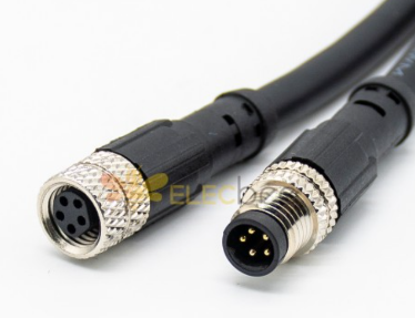
EXpand™ is a hardware concept in the Accordion™ platform which allows for versatile expansion of hardware functionality outside of the AGENT™ box. In many cases, placing functionality outside of the box can be beneficial as it gets closer to the intended usage. It also allows for more functionality that wouldn’t physically fit inside the AGENT™ box.
The connector used for EXpand™ is M8, which is a rugged cable standard for industrial electronics.
Examples of EXpand™ devices:
|
EXpand™ device |
Description |
|
DMM Relay |
Galvanically isolated relay switch/mux that allows for up to 32 channels |
|
PSU Module |
2-Channel programmable PSU, 24V/5A |
|
Fixture Comm |
A test fixture can be equipped with the EXpand™ electronics, which allows for many features directly on the fixture backplane |
|
Active Load |
4-channel programmable active load 0-24V, 0-1A |
|
PCIe Carrier |
EXpand carrier module for PCIE boards, such as PSU Module or PoE module. This can be used to house PCI Accordion modules outside of AGENT™ |
|
SO-DIMM Carrier |
EXpand carrier module for SO-DIMM boards, such as GPIO or MPIO modules. This can be used to house SO-DIMM Accordion modules outside of AGENT™ |
The frontend for EXpand™ is based on LTC4331, which is a differential I2C driver that allows for up to 60 meter cable.
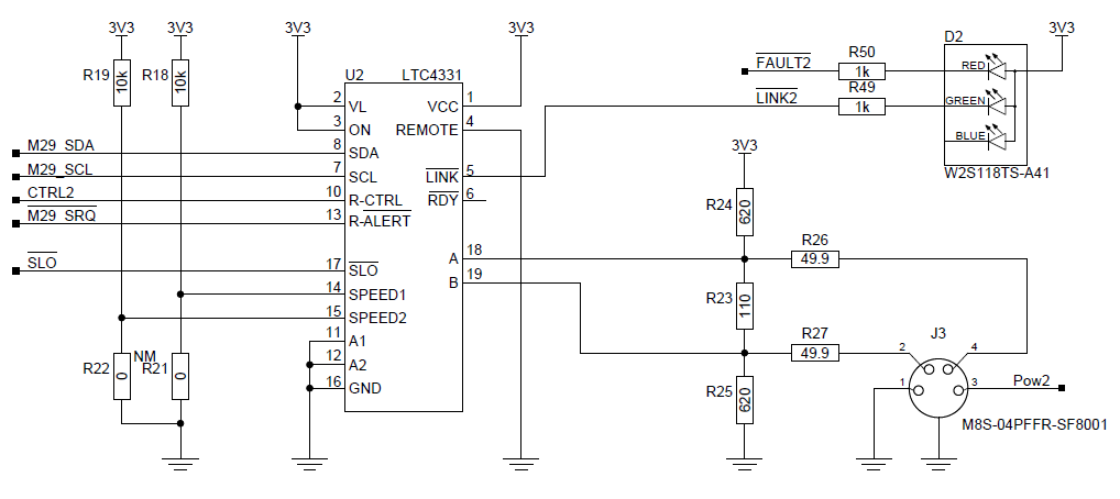
In AGENT™, the I2C-LR module provides connectivity to up to 4 downstream devices.
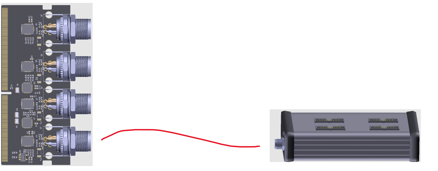
The size of the EXpand™ module can vary depending on what type it is but is generally a smaller form-factor extruded aluminum box.
AGENT Q2™
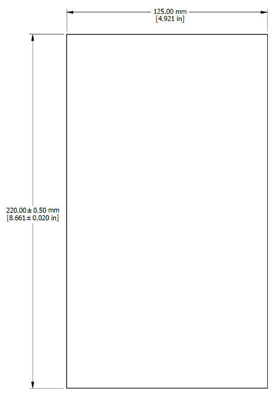
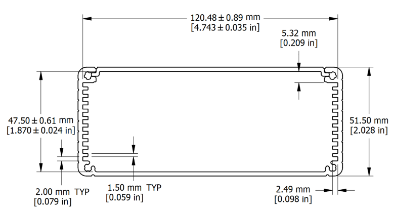
Mechanical outline
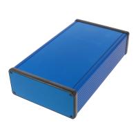
The mechanical outline of AGENT Q2 is based on an aluminum extruded enclosure 1455Q2201 from Hammond Inc.
The box is colored blue with custom sides and lid.
The size of the box allows for installation both inside and outside of the test fixture as desired.
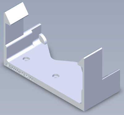
E# has developed different types of fixation methods for this box which allows it to be placed in both utility enclosures as well as inside a test fixture. There are also desktop stands and 19” rack mounts available.
Q2 Build system
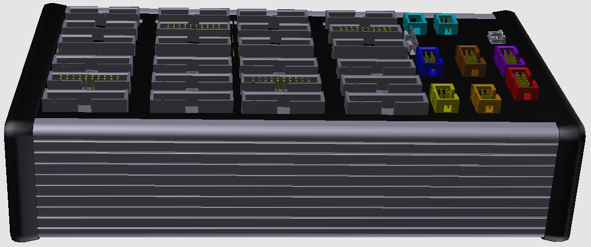
AGENT™ is one of the form factors that Accordion™ could take. As it is a modular and scalable build system, it allows for many different form factors depending on the use case.
Under the top cover, the board has many board-to-board connectors which allow customized modules (N-slot modules) to be placed.
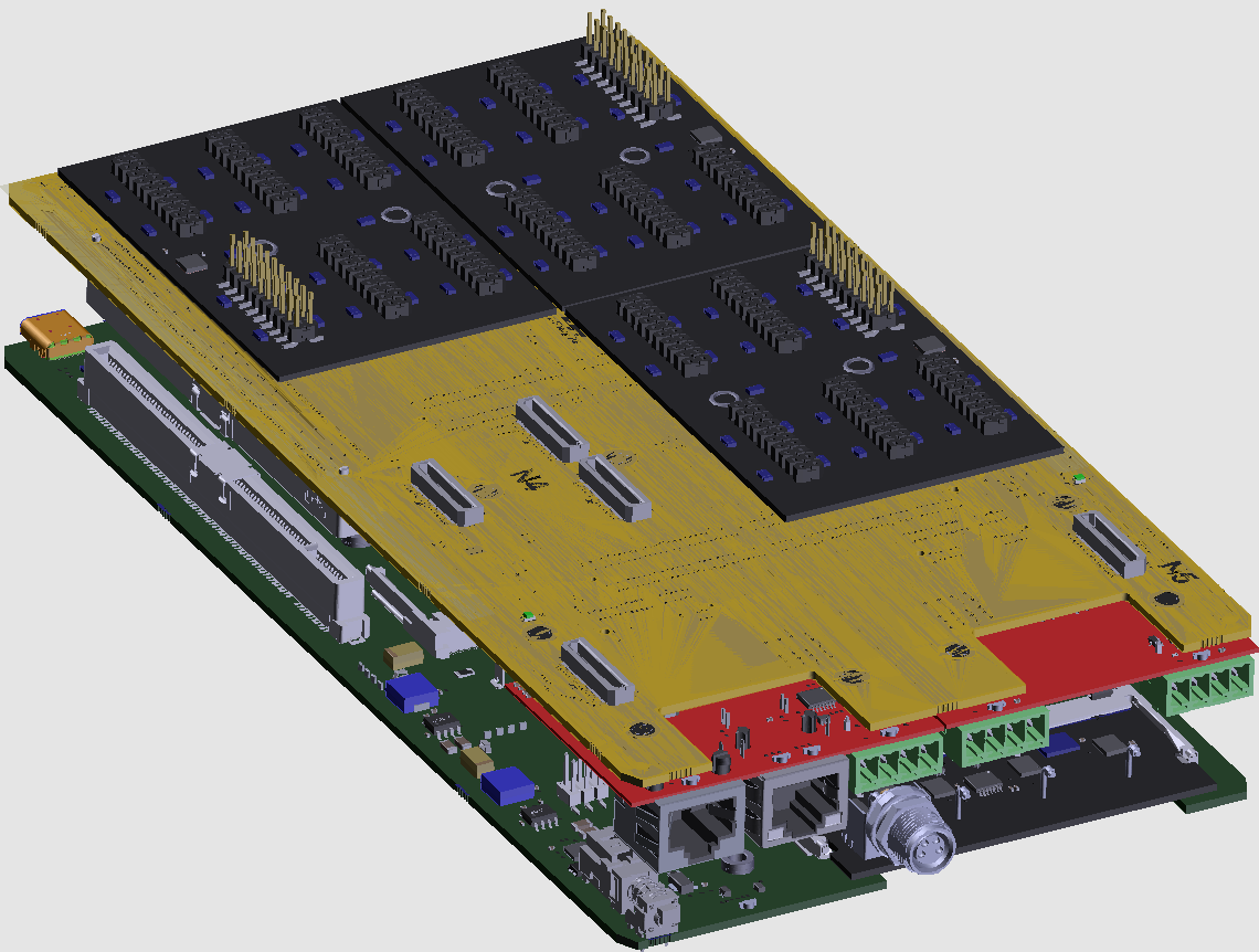
Top Board
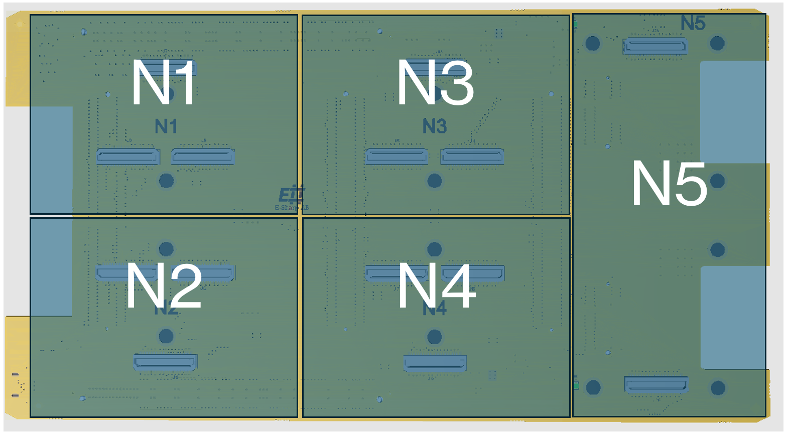
The rationale behind the N-slot modules is to be able to accommodate any type of connector that a user might want. Standard modules such as IDC connectors exist, but it is easy to make a board that fits a specific connector as well.
The N1-N4 slots are specifically designed to break out the signals coming from the SO-DIMM slots but can be used for other purposes as well as all communication buses and power available.
The N5 slot isn’t connected to any SO-DIMM slot and its main purpose is to provide different communication buses such as I2C, SPI, UART, JTAG or common fixture requirements such as fan controller or light indications.
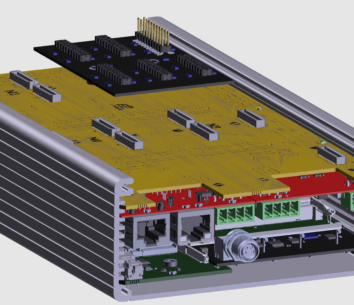
Looking on the other side of the board:
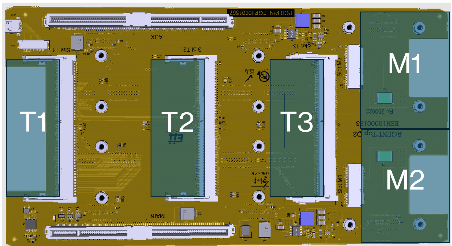
The T1-T3 slots are SO-DIMM based modules that provide the functionality or measurement capabilities to the N-slots. T1 connects with 100 user signals towards N1. Same goes for T2->N2, T3->N3 (T4 is placed on the base board but otherwise identical).
On the right-hand side, two additional module slots exist (M1/M2). The purpose of these slots is to provide power-related functionality. E# provides both programmable power supplies, active loads and Power-over-Ethernet (PoE) modules that fit in these slots.
Base board
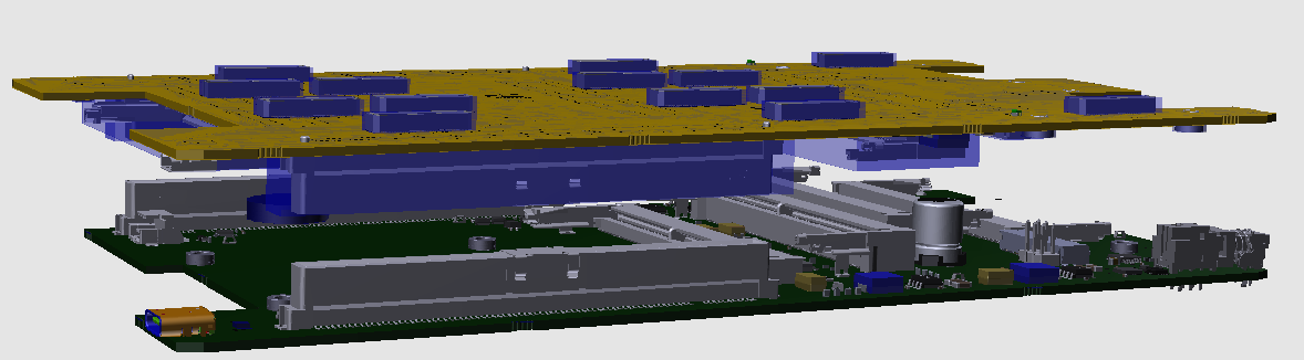
The base board hosts all subsystem functionality, such as control module, power generation and cooling to the system. The base and top board is connected together with two PCIe riser boards on each side.
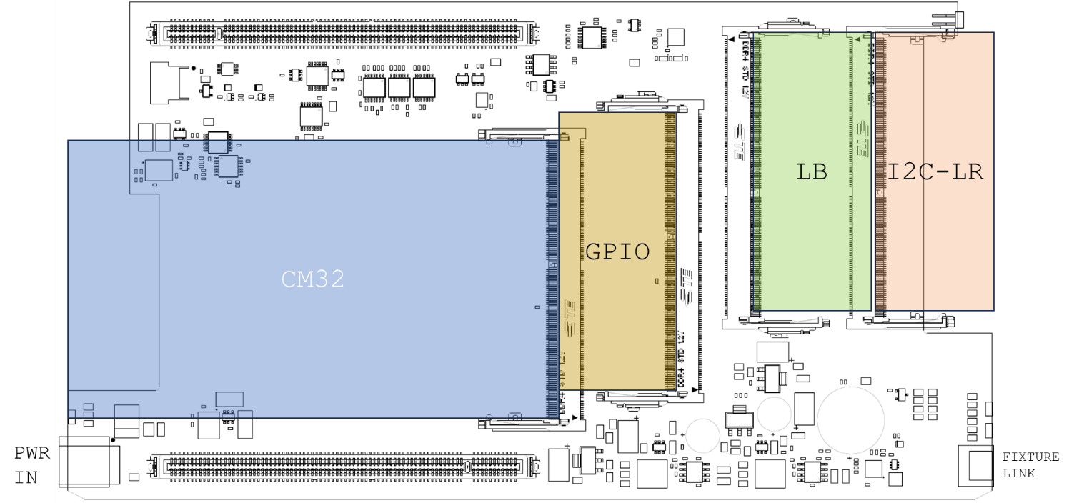
The BASE has four SO-DIMM4 slots where A1 is designed to hold the Control Module with the Rasberry PI4 that is used as a controller for the system. The Control Module is called CM32, with the “32” meaning the number of unique addressable I2C channels.
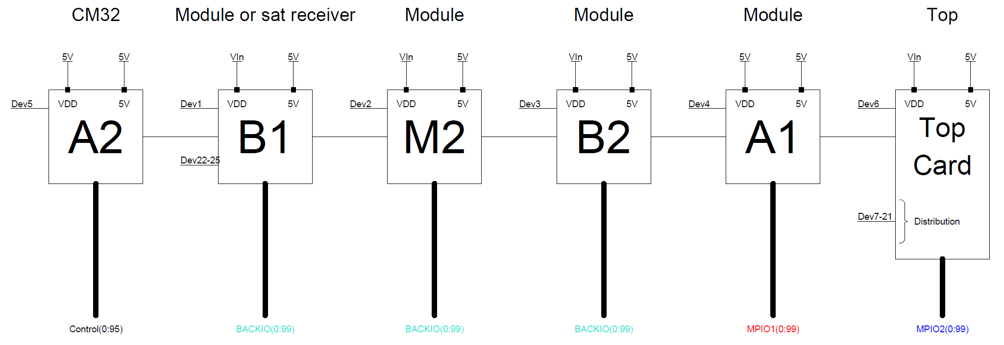
The bus- and data structure distributes system internal buses such as SPI/UART/JTAG in a daisy-chain fashion from the CM32 (A2), through the forward-facing slots B1/B2 through the middle slot A1 and then continues up to the AGENT TOP.
AGENT BASE also provides basic facilities such as power supplies for the system as well as clocks, fan control, overcurrent limiting and on/off button.
The buses are routed:
-
from the CM32 module (A2) through the first front-facing SO-DIMM (B1) which is at A-distance from the front
-
further through the M2 slot (intended for external bus communication expansion)
-
to the second front-facing SO-DIMM (B2), which is at B-distance from the front
-
then to A1 SO-DIMM in the center of the PCB. All measurement signals from this slot is routed to the N4 slot on the top board
-
Lastly, the bus reaches the top board for further distribution.
On the top board, the buses and control signals are routed in a similar fashion:
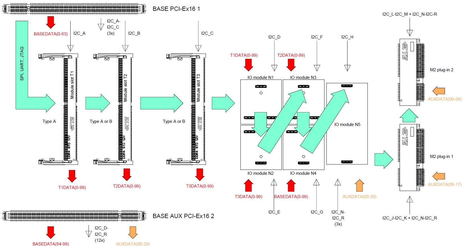
When the bus enters the top board, it is first routed;
-
To SO-DIMM (T1) which sits on A-distance from the back panel. T1 routes all measurement signals to N1
-
Further to slot SO-DIMM (T2), on B-distance from the back panel. T2 routes all measurement signals to N2
-
To the last SO-DIMM slot on the top board (T3) which sits on D-distance from the back panel. T3 routes all measurement signals to N3.
-
Then the bus is routed through modules N1-N4
-
Then to the communication module N5
-
Lastly to the two M.2. slots
Software Architecture
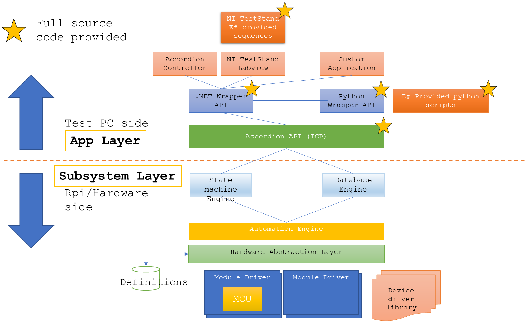
The software implementation is divided into two parts; One resides on the AGENT itself on its on-board computer, the other part is communicating with the AGENT through a proprietary TCP protocol. On the application layer, a .NET wrapper provides an API for use with NI TestStand or Labview applications. Also a python wrapper exists for the same .NET wrapper.
The ‘Channel’ concept
All functions in an Accordion system are abstracted through a ‘Channel’ concept. A channel could be anything from a Digital or analog input or output, a temperature input, a register, or a communications channel. The intention of this abstraction is to provide an intuitive interface towards complex functions.
When the Accordion system boots, a discovery process starts to find all attached hardware modules. Each module reports the channels it supports.
The ‘value’ of a channel is always represented as a string. If it is a boolean-type value (as for a digital channel), the string value is either “true” or “false”. For floating point numbers (as for an analog channel), the string value is always a value convertible from a double value with dot as a decimal separator “1.234”.
Values are always in SI units if applicable. Measuring a voltage returns the value in ‘Volts’ for example. Temperature returns the value in °C.
Channel definitions
The following channels are defined:
|
Channel Type |
Direction |
Option 1 |
Option 2 |
Option 3 |
|
Analog |
IN | OUT |
Gain |
Offset |
RSE|DIFF |
|
Digital |
OUT |
PushType |
IOVoltage |
|
|
Digital |
IN |
PullType |
|
|
|
Pseudo-Digital |
IN | OUT |
VLOW |
VHIGH |
|
|
Temperature |
IN |
SensorType |
Coldjunctiondestination |
Parameter (depending on SensorType) |
|
Multiplexer |
N/A |
|
|
|
|
Resistance |
IN |
ClampVoltage |
|
|
|
Counter |
IN |
|
|
|
|
Frequency |
IN |
|
|
|
|
Actuator |
OUT |
ToggleEnabled |
ToggleTimeMilliSeconds |
|
|
Powersupply |
OUT |
CurrentLimit |
OvercurrentResponse |
|
|
Register |
IN | OUT |
|
|
|
|
Ratiometric |
IN | OUT |
Gain |
Offset |
|
|
UART |
IN | OUT |
Baudrate |
BusType |
TerminationByte |
|
SPI |
IN | OUT |
ClockSpeed |
SpiModeTypes |
ChipEnableHigh |
|
I2C |
IN | OUT |
ClockSpeed |
|
|
|
NumericResult |
IN |
|
|
|
Analog
An analog channel can either be an input or an output. Gain and Offset settings affect how the value is converted in the form y=kx + m, where k = Gain and m = Offset.
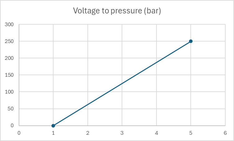
For sensors (input) or excitation networks (output) this can be very useful when working with linear systems. Say for example that you use a pressure sensor that measures the pressure in bars where 1V equals 0 bar and 5V equals 250 bar. Setting Offset = 0.5 and Gain = 62.5 gives the resulting value directly in bar’s instead of having to convert the value by hand.
When an analog signal is an output, the reversed calculation is made. This means that for a Gain of 2, it is assumed that some external amplifier doubles the signal, hence the output value from channel is halved. External attenuator can be modeled in the same way by using, for example Gain=0.5.
Digital
A digital channel can either be an input or an output. Depending on the capabilities of the module that provides the channel, it could have a configurable PushType (OpenDrain, PushPull) or a configurable PullType (None,Up, Down) depending on if it is configured as an output or an input. A digital output configured with OpenDrain means that the digital state ‘true’ will short the output to ground, and ‘false’ will render the output to be high impedance (High-Z). A digital output configured with PushPull means that the digital state ‘true’ will push the voltage up to the IO Voltage, and ‘false’ will pull the voltage down to ground.
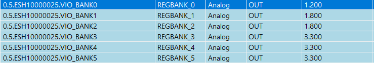
For the IO Voltage setting (if supported), it sets the IO voltage that is used with the PushPull configuration. Note that for the GPIO module (ESH10000025), the IO Voltage can’t be configured per-pin but rather per-bank (groups of 16 GPIOs) and is then controlled by another channel called ‘VIO_BANKx
When a digital pin is configured as an input, the PullType sets if there should be a pull-up resistor, a pull-down resistor or no resistor. If a pull-up resistor is selected, it is weakly pulled up to the IO Voltage. A pull-down resistor is a weak resistor down to ground. The exact resistance of these pull resistors is not defined but in the range of 100kΩ.
Pseudo-Digital
A pseudo-digital channel is a digital input or output which is backed by an ADC or a DAC.
The VLOW parameter sets the low voltage. This is the voltage that an output would take when set to ‘false’, or the upper threshold voltage for an input to convert the value to a ‘false’ value.
Similarly, The VHIGH parameter sets the high voltage. This is the voltage that an output would take when set to ‘true’, or the lower threshold voltage for an input to convert the value to a ‘true’ value.
A pseudo-digital input channel that exhibits a voltage that lies between VLOW and VHIGH will retain its last value.
Multiplexer
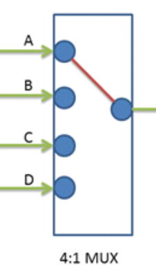
A multiplexer channel is seen as representing the common node of a multiplexer of arbitrary size and its value represents the currently selected wiper node. The multiplexer is enabled or disabled using the channel’s Enabled property.
Temperature
The temperature channel is typically an input that measures a real-world temperature and returns the value in °C. Most temperature channels are not configurable, but for example the Thermocouple module (ESH10000008) can configure what type of sensor that is attached. The possible values for the SensorType are:
|
//Thermocouples |
//RTD |
//Thermistors |
//Other |
|
TC_TYPE_J |
RTD_PT_10 |
THERM_44004 |
DIODE |
|
TC_TYPE_K |
RTD_PT_50 |
THERM_44005 |
SENSE |
|
TC_TYPE_E |
RTD_PT_100 |
THERM_44007 |
ADC |
|
TC_TYPE_N |
RTD_PT_200 |
THERM_44006 |
|
|
TC_TYPE_R |
RTD_PT_500 |
THERM_44008 |
|
|
TC_TYPE_S |
RTD_PT_1000 |
THERM_YSI400 |
|
|
TC_TYPE_T |
RTD_PT_1000_375 |
THERM_SPECTR |
|
|
TC_TYPE_B |
RTD_NI_120 |
THERM_CUST_SH |
|
|
TC_TYPE_CUSTOM |
RTD_CUSTOM |
THERM_CUST_TABL |
|
(Entries in gray are not directly supported, contact E# for more information if this is needed.)
For thermocouples, a reference cold junction must be provided, which is done with the field ‘Coldjunctiondestination’. Possible values are ‘CH<id>’ where <id> is [00 to 20] and denotes what channel that should provide cold junction measurements. Several or all thermocouple channels can be associated with the same cold junction channel.
A cold junction channel can’t in it self be a thermocouple channel, it has to be a sensor that accurately converts real-world temperature’s, such as a diode or RTD.
Resistance
A Resistance channel typically measures resistance. Resistance is measured indirectly by applying a known voltage over the load, measuring the current that flows in the circuit and by that calculate the resistance using ohms law.
Counter
A Counter channel counts pulses. To reset the counter, the channel could be disabled and re-enabled.
Frequency
A Frequency channel could either be an input or an output (i.e. measure or generate a frequency).
Actuator
An actuator channel is similar to a Digital output channel but has the additional capability of toggling the signal with a specific interval. If the ‘ToggleEnabled’ field is set to ‘true’, the channel will toggle back into its default value after ‘ToggleTimeMilliSeconds’ has elapsed.
Power Supply
A PowerSupply channel is used by a Power supply to configure its output. Enabling/disabling the channel corresponds to turning the power supply output on/off. The value of the channel sets the output voltage expressed in volts.
‘CurrentLimit’ sets the current limit (if supported) of the power supply and ‘OverCurrentResponse’ sets how the power supply should react if the ‘CurrentLimit’ is reached. ‘OverCurrentResponse’ can either be ‘Off’ (turn off power supply output) or ‘Limit’ (enter constant-current mode).
Register
A Register channel is a channel type that handles all other aspects that is not covered by the other channel types. A typical case for a Register channel usage is exposed chip registers (byte-oriented) or string-based values that can be set or read.
Ratiometric
A ratiometric channel is used for a value that is relative (ratiometric) to another property. The value is typically between 0-1 (0-100%). An example is fan setting, where the fan is regulated between 0-100% of its capacity.
UART/SPI/I2C
These channels are specific to bus communication and can’t be read or set directly but rather from the ‘Bus Communication’ tab page.
NumericResult
A NumericResult channel is related to multi-sample measurements and can’t be read or set directly but rather from the ‘Chart’ tab page.
Software modularity
Just as the hardware build system is modularized, the software- and firmware is too.
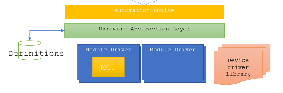
Each hardware module has its own EEPROM that stores the module type. Upon booting, the subsystem scans all possible locations and discovers the attached modules. Upon enumeration, the associated module drivers are loaded and the implemented ‘channels’ are exposed to the user.
The subsystem also allows for additional software module that can support a vast number of applications. This concept is called Accordion Extension Modules (AEM). A user can load- or unload an AEM at any point and the AEM acts as a module just as an installed hardware module would do. It is for example to implement stand-alone controllers for MODBUS, CAN-bus or custom bus protocols which E# have implemented for customers. E# solution for automating PMBUS devices is implemented as an AEM. E# also has AEM modules for controlling SCPI-based instruments, LED analyzers such as FEASA or Temperature chambers.
Interactive debug
Interactive debug is made possible because AGENT™ manages the connection as a TCP server, which accepts connections from many sources simultaneously. This means that both TestStand can be attached at the same time as the user is connected through the Accordion Controller application.
Using Accordion from NI TestStand
Using Accordion from NI TestStand is easy. The .NET wrapper dll provides an easy to use API with statically implemented methods so no instantiation is needed.
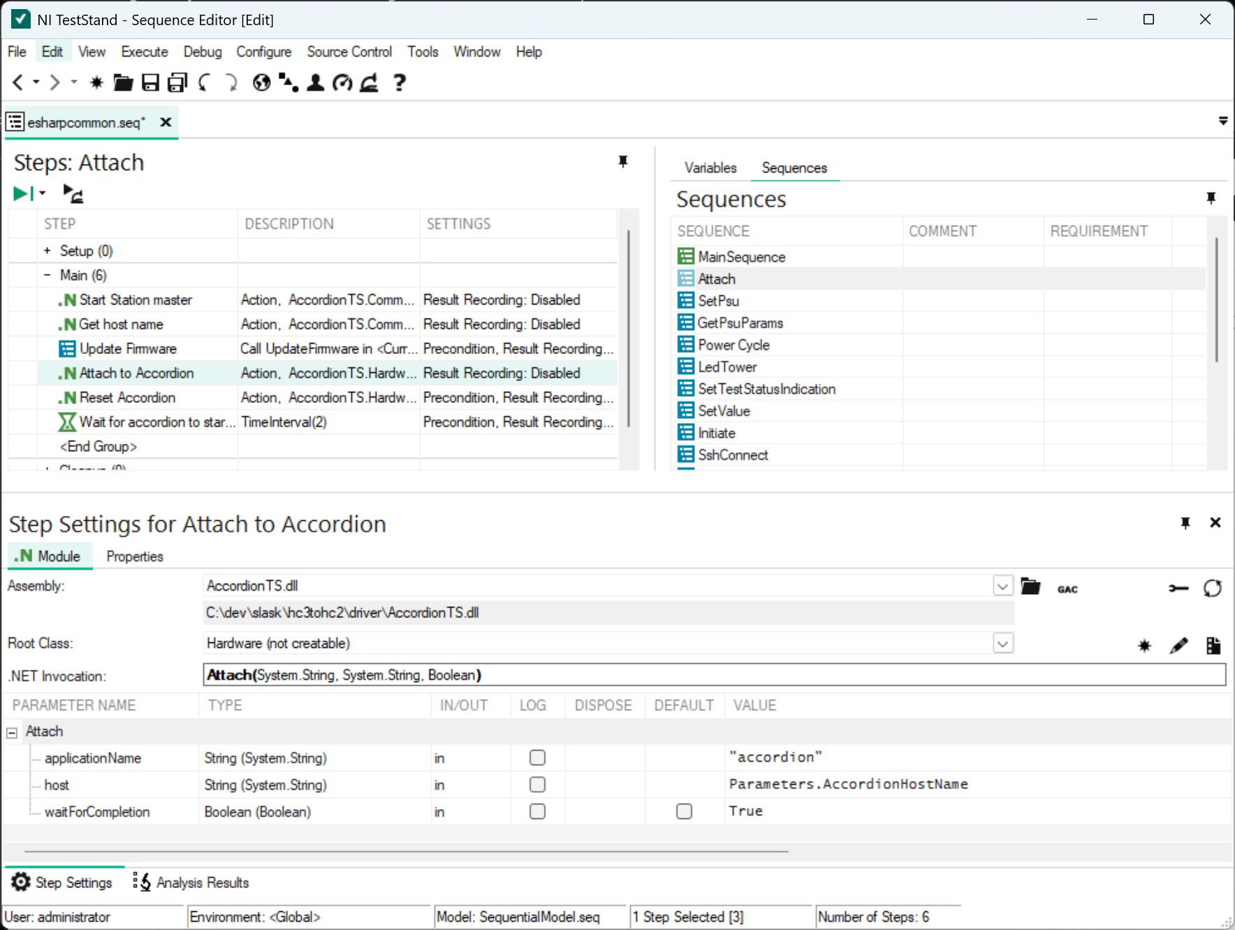
The API also ships with an esharpcommon.seq that can be used to access common functionality such as initialization, firmware update, Power supply control, LED tower control and so on.
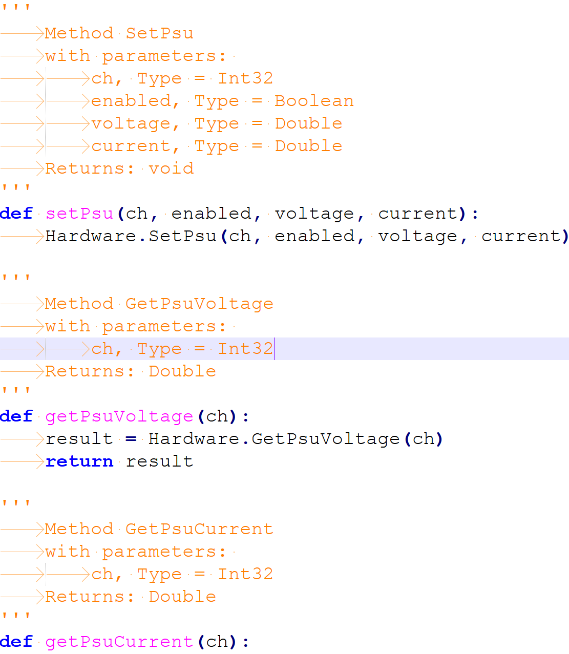
Using Accordion from python
It is also possible to use Accordion from python. The same .NET wrapper API is exported as a python wrapper and it is automatically generated when running the shell application.
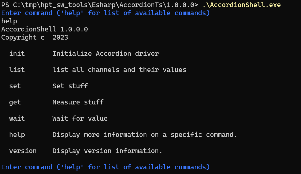
Using Accordion from command-line
It is also possible to use Accordion from a command-line window.
C# API
E# distributes two version of the same API, both for .NET4.8 and .NET8. The .NET48 version is supplied to be compatible with NI TestStand or other legacy software.
The API is designed to be as light-weight as possible, yet incredible powerful.
In essence, there are four main categories in the API:
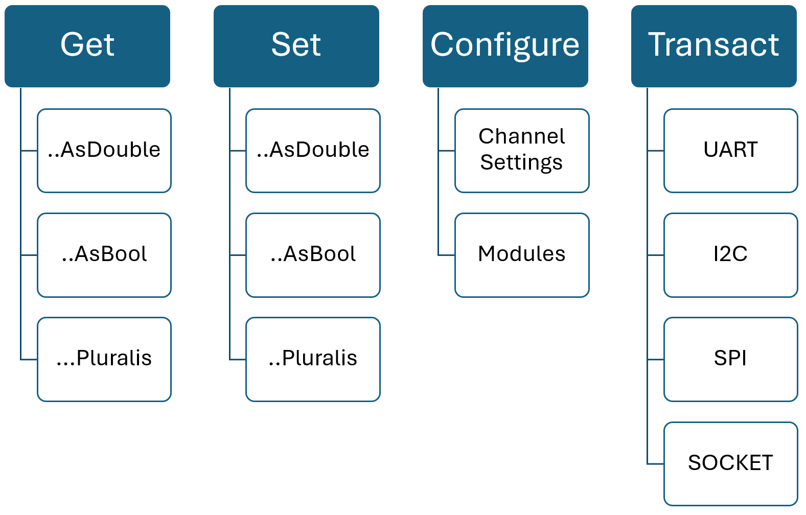
Together with the channel abstraction concept, you can “get” a value from any channel. Actually, it doesn’t matter how the channel is configured or what type of channel it is, there are always a value associated with a channel. In its core, the method is simply:
string[] GetValues(string[] names)
For convenience, there are singular- or plural methods as well as built-in conversions from string to a specific value type in the API. But the transaction that happens over the network is simply a string representation of each value.
Similarly, some channels can be ‘set’ to a value. That depends of the direction of the channel, a DirectionType.IN can only be ‘get’:ed. In the same way as for the ‘get’ command, there are convenience methods for value type conversion.
void SetValues(string[] names, string[] values)
For both the set/get methods, the order of values is imperative. If you specify “1”, “2”, “3” in the channel names, this is also the order of the returned values for those channels.
The third API category is used to configure stuff. A channel might be configurable to be either an input or an output. A channel might even be configurable to a different channel type. An example of this is a MPIO channel, that could be configured as either an Analog channel or a PseudoDigital channel. It could also be configured as an input or an output.
void ConfigureChannels(IEnumerable<IMultiPurposeChannel> channels)
In the configure bucket, we have a few system-related functions such as Reset, Identification and such.
As for modules, they can be either listed, loaded or unloaded. Example:
void LoadModule(IModuleSettings module)
The last category is the transaction methods, in its core:
IBusTransaction PerformBusTransaction(IBusTransaction t)
When you think about it, all communication buses share the same traits: You want to perform a certain action on the bus (send/receive/scan/break), sometimes with sending some kind of data and sometimes receiving data. In the Accordion API, all bus transactions are wrapped as a IBusTransaction. The specifics of each bus is provided by more specific interfaces (such as II2cTransaction) that inherits from IBusTransaction.
Python API
The python API is just a wrapper around the C# API and provide the same functionality with similar syntax. Actually, the python wrapper API is auto-generated from the C# API to ensure consistency between the two.
Contact Information
This document and the products described in this document are written and developed by E-Sharp AB.
Email address: support@esharp.se
Adress: Götgatan 3, 244 32 Kävlinge