

Product Brief
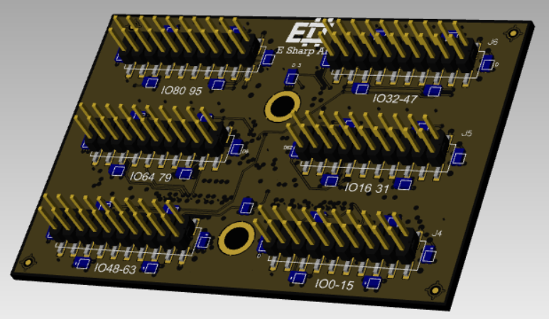
The ESH10000355 is an Accordion N-TOP module providing high-density signal breakout via six IDC 20-pin connectors, exposing 96 user signals (DATA[0–95]) directly from the Accordion DATA bus. It is designed for use in PCBA test, NPI, and production test environments where rapid fixture integration and direct signal access are required.
The module occupies a single N-TOP slot on the Accordion or Accordion A2 top board. Signals are routed 1:1 from the system DATA bus to the IDC connectors — no active components, no signal conditioning. The module is passive.
Typical use cases:
-
Signal breakout to PCBA test fixtures via IDC ribbon cable
-
High-density digital/analog channel access in automated test systems
-
Interface to custom or standard test adapters
-
Direct channel-to-pin mapping for fixture design and debug
Datasheet
|
Parameter |
Value / Description |
|---|---|
|
Module Type |
N-TOP (Accordion) |
|
Part Number |
ESH10000355 |
|
User Signals |
96 (DATA[0–95]) |
|
Connector Type |
IDC 20-pin (×6), 2.54 mm pitch |
|
Connector Designators |
J1 – J6 |
|
Signal Mapping |
Direct 1:1 to Accordion DATA bus |
|
Compatible Systems |
Accordion, Accordion A2 |
|
Form Factor |
N-TOP slot module |
|
Max Voltage |
5V |
|
Max Current |
2A |
|
ESD Protection |
IEC 61000-4-2
|
Manual
Hardware
Installation
-
Power down the Accordion or Accordion A2 system before inserting or removing modules.
-
Align the ESH10000355 with an available N-TOP slot (N1–N4). The module is keyed — do not force insertion.
-
Press firmly until the module is fully seated.
-
Connect IDC ribbon cables to J1–J6 as required by the fixture design.
Slot and SO-DIMM Mapping
The N-TOP slot determines which SO-DIMM connector (T1–T3, A1) carries the DATA signals from the top board.
|
N-TOP Slot |
SO-DIMM |
|---|---|
|
N1 |
T1 |
|
N2 |
T2 |
|
N3 |
T3 |
|
N4 |
A1 |
Signal Routing
Each IDC 20-pin connector (J1–J6) exposes 20 DATA lines. Signal assignment is fixed by the module PCB layout. See the Pinout section for per-connector, per-pin signal mapping.
Example: If an MPIO module (e.g., ESH10000590) is installed in slot A1 and ESH10000355 is in N4, MPIO channel A1/0.5 is routed to DATA0, which is accessible at J4 pin 3.
Cabling
Use standard 20-pin IDC ribbon cables. Ensure cables are fully seated and latched. Verify pin 1 orientation (marked stripe on ribbon) matches the connector key.
Software
The ESH10000355 is passive — it requires no driver and has no configurable parameters. All software interaction is against the source channel (MPIO, MADC, etc.) routed through the DATA bus.
Channel Access
Channels are addressed by their logical name in the Accordion system. Use the channel discovery API or the system's channel map to identify which logical channel corresponds to each physical pin.
C# (.NET API)
// Read digital value from channel mapped to DATA0
var value = pilot.GetChannel("DATA0").ReadDigital();

// Write digital value
pilot.GetChannel("DATA0").WriteDigital(true);
Python
# Read digital value from channel mapped to DATA0
value = pilot.get_channel("DATA0").read_digital()

# Write digital value
pilot.get_channel("DATA0").write_digital(True)
TestStand
Use the provided Accordion sequence files. Reference channels by name in the ChannelName parameter of the Accordion step types. No additional configuration is required for the ESH10000355 itself.
Channel Discovery
// List all channels available in the system
var channels = pilot.GetChannels();
foreach (var ch in channels)
    Console.WriteLine(ch.Name);
Pinout
The module has six IDC 20-pin (2×10, 2.54 mm pitch) connectors. Each connector exposes 20 DATA lines. Pin 1 is indicated by the chamfer and by the marked wire on standard IDC ribbon cables.
Connector Overview
|
Connector |
DATA Lines |
|---|---|
|
J1 |
DATA[0–15] |
|
J2 |
DATA[16–31] |
|
J3 |
DATA[32–47] |
|
J4 |
DATA[48–63] |
|
J5 |
DATA[64–79] |
|
J6 |
DATA[80–95] |
Pin Mapping (per connector)
IDC 20-pin connectors use a 2×10 layout.
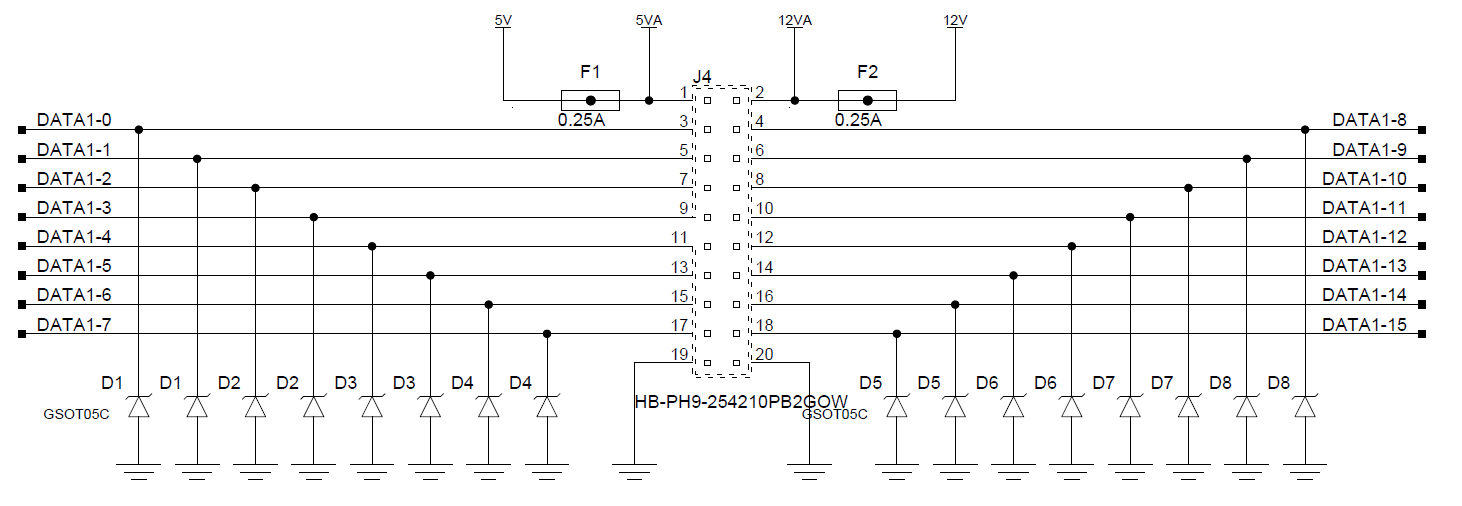
GND and Power Pins
Pin 1 is 5V with a thermistor fuse (0.25A)
Pin 2 is 12-20V with a thermistor fuse (0.25A)