

Product brief
The ESH10000534 is an IEEE 802.3bt–compliant Power over Ethernet (PoE) Power Sourcing Equipment (PSE) module in M.2 form factor. It provides a single four‑pair PoE port capable of delivering up to 90 W (Class 8 / Type 4) to a connected Powered Device (PD).
The module is designed for use in PCBA test systems, production fixtures, and PoE validation environments where controlled power delivery, detailed telemetry, and fault observability are required. It integrates:
-
PoE negotiation, classification, and protection via a dedicated PSE controller
-
Real‑time voltage, current, and power monitoring
-
Visual status indication for rapid diagnostics
-
A channel‑based control and telemetry interface suitable for automated test systems
Typical use cases include:
-
PoE compliance and margin testing
-
Power and inrush characterisation during NPI
-
Production test fixtures requiring deterministic PoE behaviour
-
System‑level validation of high‑power IEEE 802.3bt devices
Datasheet
|
Parameter |
Value |
Notes |
|
Module type |
PoE PSE module |
Instrument classified as PoETester |
|
Form factor |
M.2 |
User‑facing connector managed externally |
|
PoE standards |
IEEE 802.3af / 802.3at / 802.3bt |
Full bt support |
|
Maximum output power |
90 W |
Class 8, Type 4 (QP90W) |
|
Port configuration |
Single port, 4‑pair |
Internally mapped as channels 1–2 |
|
Input voltage range |
42–57 V |
PoE supply requirement |
|
Current measurement |
2 × 0–3 A |
Per‑pair group |
|
Power telemetry |
Per‑channel and total |
Calculated from measured current and voltage |
|
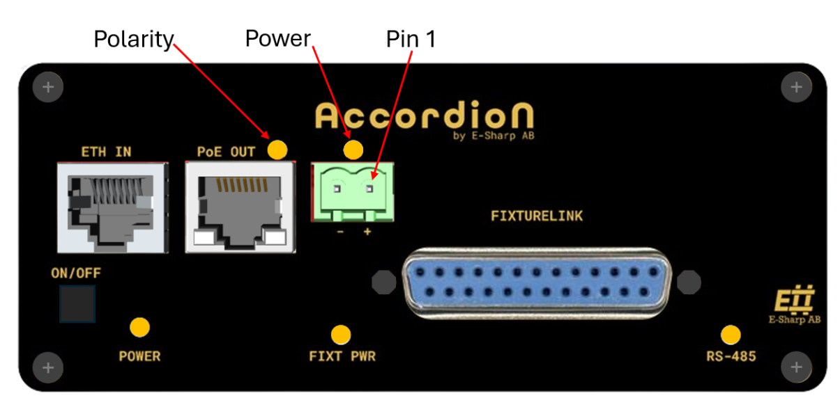
Visual indicators |
2 × RGB LEDs |
POLARITY, VIN STATUS |
|
User‑accessible channels |
~125 |
Instrument, telemetry, and register channels |
Manual
Hardware usage
Requirements:
-
External PoE supply in the range 42–57 V
-
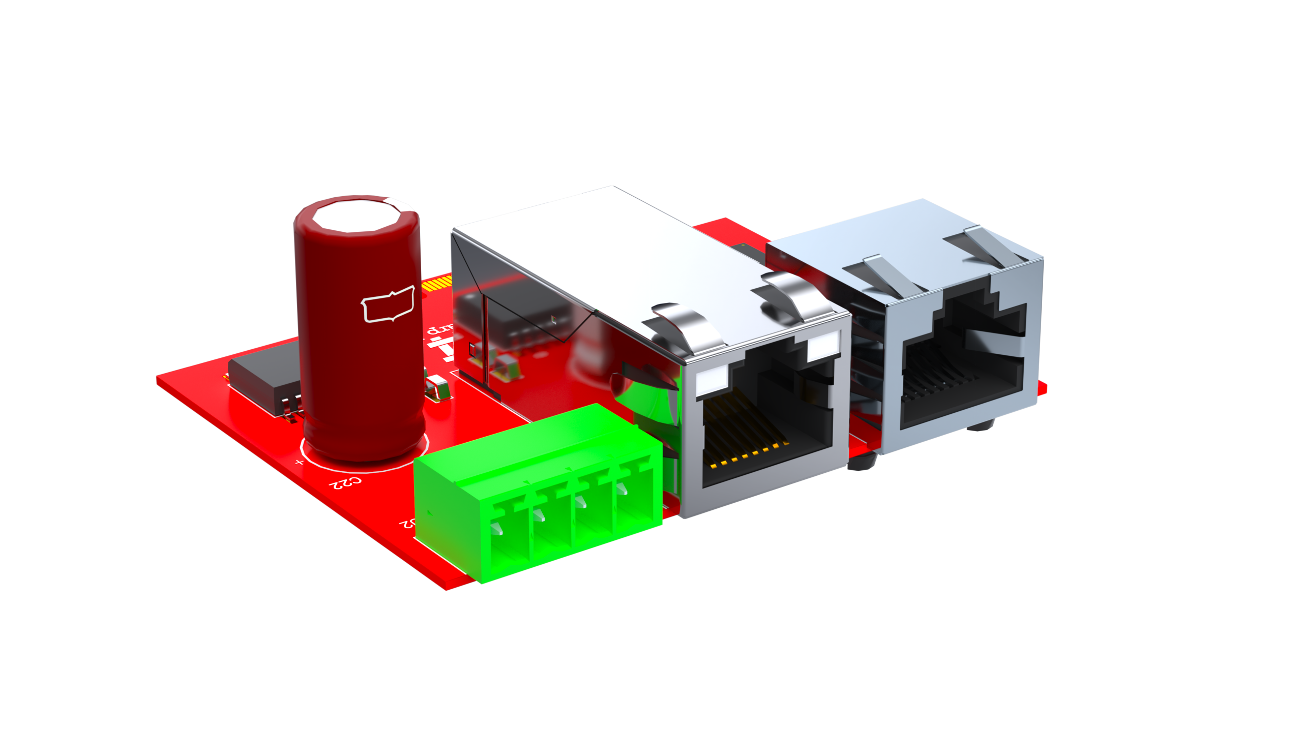
Ethernet magnetics and connector implemented in the carrier system
-
Adequate thermal management when operating near 90 W
Operational notes:
-
PoE initialisation will fail if input voltage is below 42 V
-
The module always treats the port as a four‑pair PoE port
-
Power delivery is inhibited until detection and classification succeed
LED‑based diagnostics:
-
VIN indicates input voltage validity (> 42 V / < 42 V)
-
ETH_OUT_R / ETH_OUT_L indicate PoE initialisation, operational state, or fault
-
LEDs change colour during configuration, telemetry access, and fault conditions
Software usage
The module exposes all functionality via named channels following this pattern:
{ModuleIndex}.ESH10000534.{ChannelName}
Example:
0.ESH10000534.PowerStatusRegister.PG1
Basic PoE bring‑up (typical sequence)
-
Set operating mode to
Auto -
Select appropriate power allocation (e.g.
QP90W) -
Enable auto‑class if precise negotiation is required
-
Enable detection, disconnect detection, and power
-
Verify
PG1/PG2and telemetry values
Key channels used during normal operation:
-
OperatingModeRegister.CH1 / CH2 -
PortPowerAllocationRegister.CH1 / CH2 -
PowerEnableRegister.CH1 / CH2 -
DetectClassEnableRegister.CH1 / CH2 -
TELEMETRY.*
Telemetry and monitoring
Available telemetry includes:
-
Per‑channel current and power
-
Total current and power
-
Min/max current tracking for inrush analysis
-
Input voltage monitoring
Peak tracking must be explicitly cleared using TELEMETRY.CLEAR_PEAKS before a new measurement window.
Fault handling
The TPS23881 exposes detailed fault and event registers. Common conditions to monitor:
-
Overcurrent (tOVLD / tLIM)
-
Start‑up timeout (tSTART)
-
Thermal shutdown
-
Supply under‑/over‑voltage
-
PD disconnect events
Faults do not automatically clear in all operating modes; behaviour depends on selected mode (Auto, SemiAuto, Manual).
Pinout
|
Pin |
Name |
Description |
|---|---|---|
|
1 |
PWR |
Isolated power for PoE (+56V) |
|
2 |
GND |
Isolated power for PoE (GND) |