

Product brief
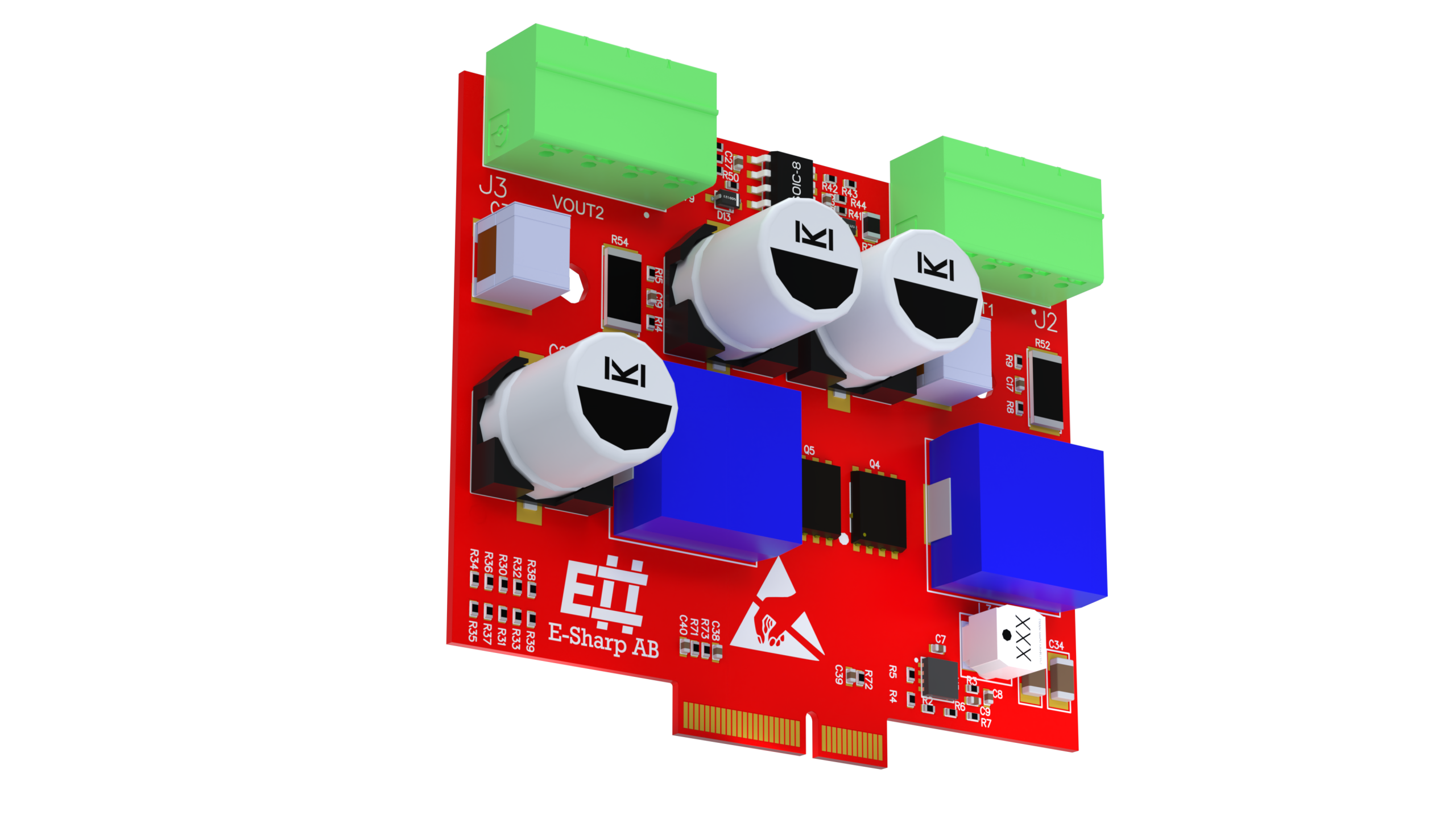
The ESH10000533 is a dual-channel, programmable power supply module intended for M.2 device test, validation, and production environments. It provides two fully independent DC/DC outputs with PMBus control, designed to be driven from Accordion-based test systems and automated software environments.
Typical use cases include:
-
Powering M.2 DUTs during PCBA test, NPI, and volume production
-
Dynamic voltage control and margin testing during functional verification
-
High-resolution current, voltage, and power telemetry for diagnostics
-
Automated fault detection and protection handling in test sequences
The module is built around the Linear Technology LTC3889 PMBus controller and exposes its functionality through a consistent channel-based interface. All configuration, control, telemetry, and calibration are performed via software; no manual adjustments are required during normal operation.
Datasheet
Electrical specifications
|
Parameter |
Value |
Notes |
|
Channels |
2 (CH1, CH2) |
Fully independent |
|
Max output power |
60 W in total |
Power derated, total output power |
|
Output voltage |
0-20V |
|
|
Output current |
0-10A |
|
Protection features
|
Protection |
Description |
|
Overvoltage |
Warning and fault levels per channel |
|
Undervoltage |
Warning and fault levels per channel |
|
Overcurrent |
Warning and fault levels per channel |
|
Temperature |
Over-/undertemperature with configurable response |
|
Startup timing |
TON_MAX fault supervision |
Telemetry
|
Quantity |
Source |
|
Output voltage |
READ_VOUT |
|
Output current |
READ_IOUT |
|
Output power |
READ_POUT |
|
Input voltage |
READ_VIN |
|
Input current |
READ_IIN |
|
Temperature |
READ_TEMPERATURE_1 / 2 (max reported) |
Manual
System integration overview
ESH10000533 is controlled entirely via software channels. Each PMBus register is mapped to a named channel using the convention:
{ModuleIndex}.ESH10000533.{Address}.{Channel}
Example:
-
0.ESH10000533.0x4F.CH1.VOUT_COMMAND
The module is typically used via Accordion API wrappers from C#, Python, or TestStand.
Basic operation flow
-
Configure input voltage thresholds (VIN_ON / VIN_OFF)
-
Configure output voltage, limits, and protection
-
Clear any existing fault state
-
Enable output using OPERATION
-
Monitor telemetry and status registers
-
Disable output when test step completes
Setting output voltage
The primary control parameter is VOUT_COMMAND per channel.
Conceptual flow:
-
Write voltage setpoint
-
Enable channel using
OUTPUT_ENABLE
No additional sequencing is required unless explicitly configured via TON/TOFF registers.
Calibration
The module exposes a dedicated CALIBRATION capability
Characteristics:
-
Persistent across power cycles
-
Applied automatically at startup
-
Per-channel current sense gain and temperature coefficient
-
Input current calibration supported
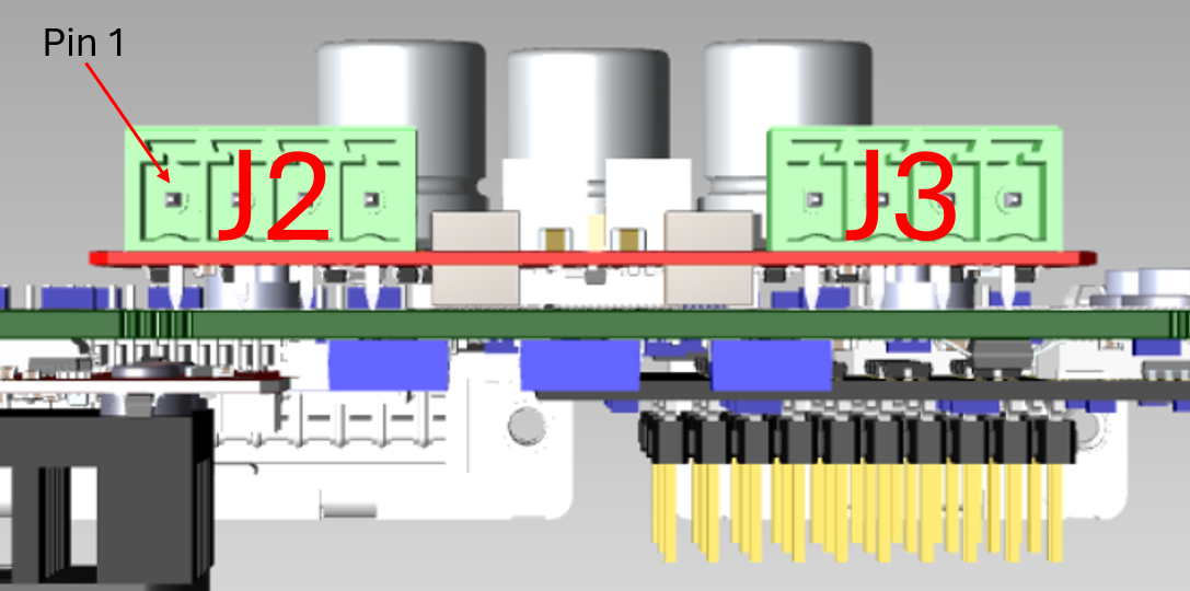
Pinout
Pin
|
Name
|
Type
|
Description
|
|---|---|---|---|
J2_1
|
VPSU_0
|
-
|
Settable Power Supply, Channel 0.
|
J2_2
|
VSENSE+_0
|
Input
|
Remote sense for positive terminal, Channel 0.
|
J2_3
|
VSENSE-_0
|
Input
|
Remote sense for negative terminal, Channel 0.
|
J2_4
|
GND
|
-
|
Common Ground.
|
J3_1
|
VPSU_1
|
-
|
Settable Power Supply, Channel 1.
|
J3_2
|
VSENSE+_1
|
Input
|
Remote sense for positive terminal, Channel 1.
|
J3_3
|
VSENSE-_1
|
Input
|
Remote sense for negative terminal, Channel 1.
|
J3_4
|
GND
|
-
|
Common Ground.
|